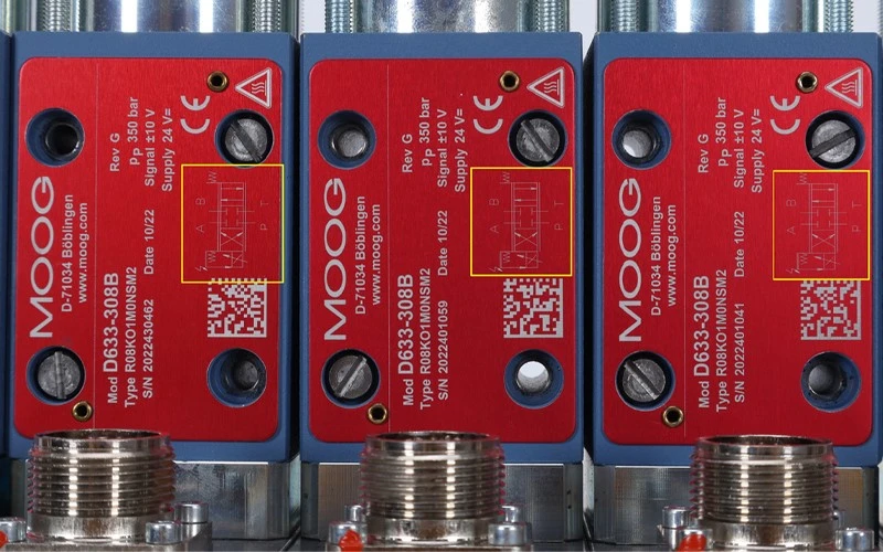
Hydraulic directional control valve
Directional control valves that is, directional valves, in the hydraulic system play a role in preventing and guiding the fluid flow in accordance with the specified direction of flow in and out of the channel, that is, in the oil circuit plays a role in controlling the direction of fluid flow. There are two important concepts in the directional valve, namely, bit and through. Bit, refers to the directional valve spool has a few working position, in the sketch with a square to indicate the position; through, refers to a few inlet and outlet ports, in the sketch with an arrow to indicate the inlet and outlet ports.
Hydraulic directional valve in the bit and through, how to identify a few bits and a few through?
So how to identify the hydraulic valve is a few bits and a few pass? Hydraulic directional valves in the more common is the two (left, right) and three (left, right, center), each working position when the flow direction of the oil is different; a few pass actually refers to the directional valve connected to a few tubes, common two-way, three-way, four-way and five-way. There are a few squares on behalf of a few valves, there are a few ports on behalf of a few valves, together known as a few several valves. Such as two-position two-way valve, three-position four-way valve. In the sketch, we can see how many symbols with vertical lines separated by the "square", there are a few is a few. And then look at one of the squares in a few with the "square" border intersecting the vertical line, there are a few is a few passes. One of the arrows indicates access (direction of liquid flow), an arrow indicates two-way, that is, into the oil and oil, two arrows is four-way; ┴ and ┬ and the intersection of the box indicates that the access is blocked by the spool. If there are two arrows and one ┬ in one box in the figure, it means five-way, one blocked.
Graphical Symbol Meaning
1, bit - with the square "□" that a few bits that is a few squares.
2, the first and last arrow ↑ and blocking symbol ┴ and a square with a few intersections that is a few passes. ↑ means that the oil port is connected, the direction does not indicate the actual flow. ┴ means that the oil port is not accessible.
3, P, A, B, T, O have a fixed orientation, P - oil inlet; T, O - back to the oil port; A, B - connected to the executive element with the working oil port
4, spring - W, drawn on both sides of the grid
5, the normal position three-position valve, the center of the grid; two-position valve, by the spring of the grid. (In the schematic diagram, the oil circuit should be connected in the normal position).
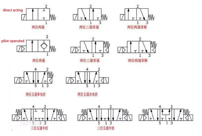
In the solenoid valve body is usually labeled with hydraulic symbols schematic, we can use the above schematic to identify is a few position several-way directional valve.